This content was created for an older version and is outdated. Check version 2 for an up-to-date description!
Primary Buffer Panel v1 (the ugly)
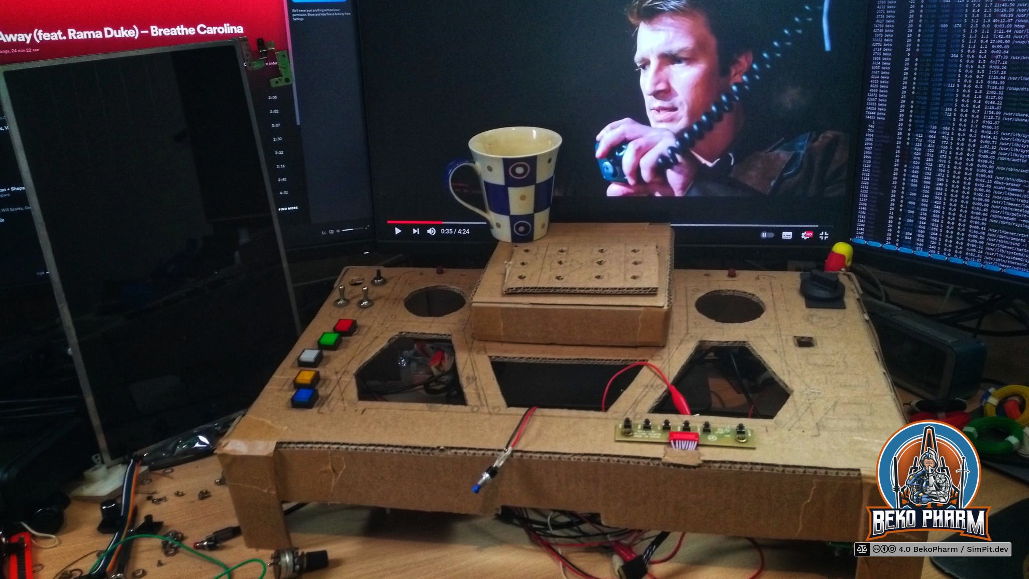
The first version of the Primary Buffer Panel was a prototype made of cardboard. It’s an excellent forgiving material that allows for rapid prototyping. I played on this for almost two years and tweaked and extended it again and again. It was eventually disassembled and the parts salvaged for version 2
I learned a lot during that time. Especially what I wanted from a cockpit (and what not). I totally recommend this approach especially when the own build is for Sci-Fi Pew Pew and not a reproduction of something that exists. This is because what we usually get to see in Sci-Fi movies or games looks awesome on first glance but is usually not functional at all. As in ergonomics, options or even overview. I’m not a designer but the shortcomings of most panels become obvious when trying to operate one in a realgame scenario where pushing buttons is not just for effect.
Subsections of Version 1
Inspiration
1.0 4.0
Obsolete content
This content was created for an older version and is outdated. Check version 2 for an up-to-date description!
YouTube videos. Not kidding. While doing research on head tracking for version 0 I stumbled over the awesome SimPits of Jaguar’s Afterimage Flightand the great C-Pit 101.
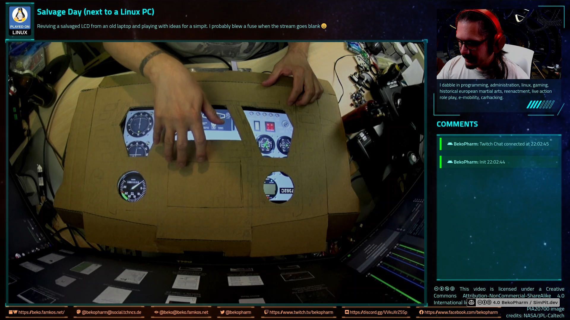
Both inspired me to eventually try rolling my own and to make sure I’d really pull it off I grabbed my camera and started streaming the whole process on twitch.tv/bekopharm. Random trivia: Me cutting cardboard apparently sounded like some trash metal band. I disputed the strike but nothing came of it, as expected.
Later, already some weeks into the build, I also stumbled over Jon’s blog and his Creative Geek channel. Jon had the same idea to use Node-RED for the plumbing and I was delighted to see another Elite Dangerous cockpit made of cardboard in the wild.
Yeah, and at some point I got tired of calling it just “button box”. It’s not. It’s a “glorified button box mock-up with a gorram LCD made from cardboard”. So I decided that it needs a name and as a nerd I came up with… Primary Buffer Panel!
This content was created for an older version and is outdated. Check version 2 for an up-to-date description!
When I started I was looking for something generic and not specific for a single game. After all I do play a lot of different Space Pew Pew.
I’m not a designer though and designing user interfaces is hard. For example what we usually get to see in Sci-Fi movies or games looks awesome on first glance but is usually not functional at all. As in ergonomics, options or even overview.
There are places that have some good pointers, on this topic, like www.hudsandguis.com, that also has a book (which I found lacking but I’m not really the targeted audience).
In the end I ended up with a wild mix of elements from shows like Battlestar Galactica, real jets and other planes and even from The Expanse and Alien.
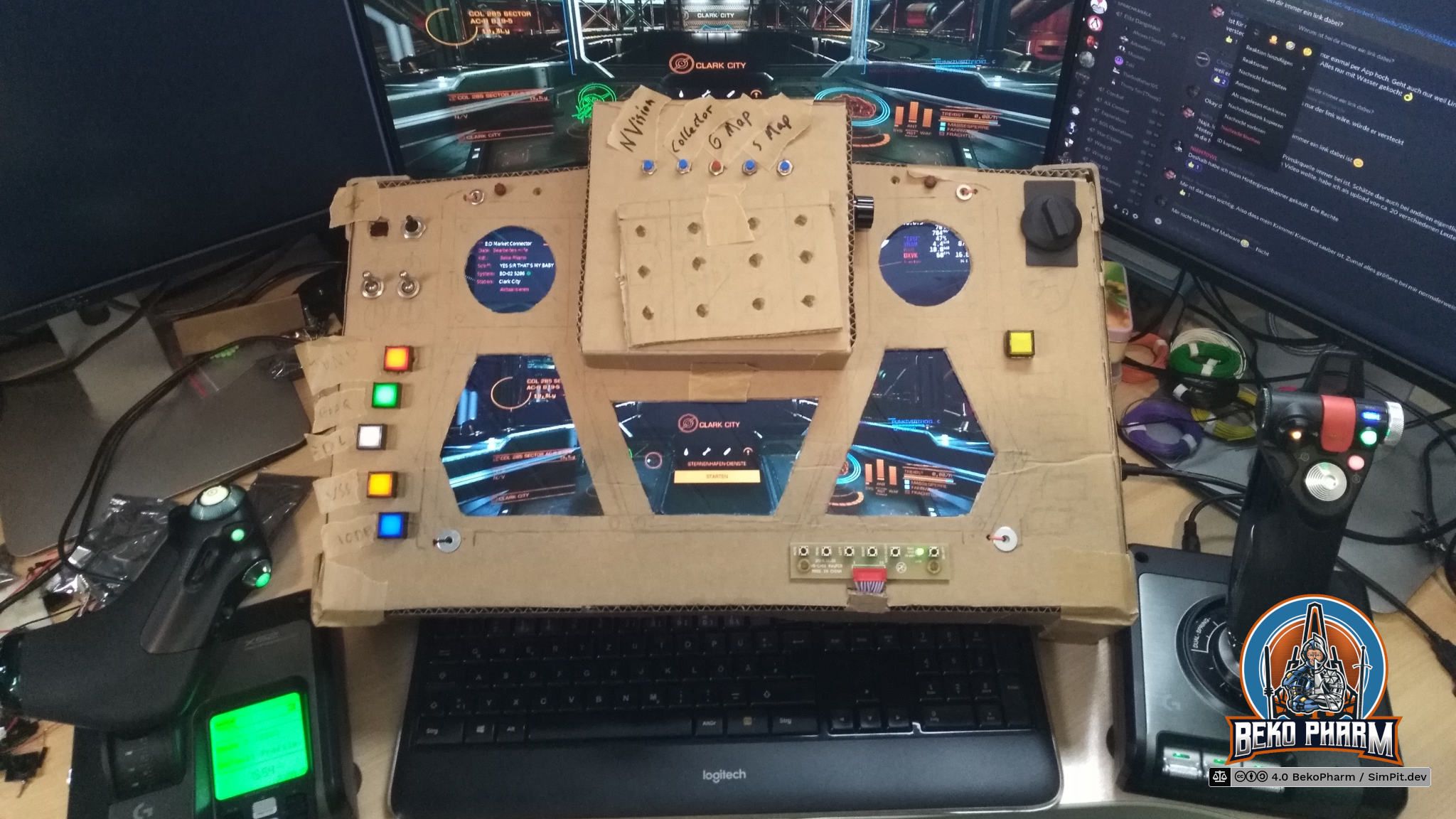
Most important were the backlit buttons for me. Did I mention that I like “real” buttons? Something with tactile feedback? Blame my childhood for this. I grew up with buttons on everything and the most fanciest displays ever: Vacuum Fluorescent Displays. I even fiddled around with CSS effects to mimic a VFD (in places - all was just too much).
I also added hexagonal status indicators, because nothing says Sci-Fi more than hexagons, to the mix. In case you wonder if I used a 3D printer for that: Nope. That’s basically a plastic cap for protecting the bolts of the rim of a car wheel. I just cut off the cap and stuffed a LED inside. Didn’t even glue them together. A wire fixed all in place which allowed me to move the segments around. They were never attached to the panel.
For starting everything up I used a multi staged switch that I salvaged from an old heater. We all know that any plane/craft in movies starts after switching the three magic levers. This was mine 🤓
The panel itself was put on stilts for the extra room required. This had the nice bonus that the keyboard could slide under the panel when not needed.
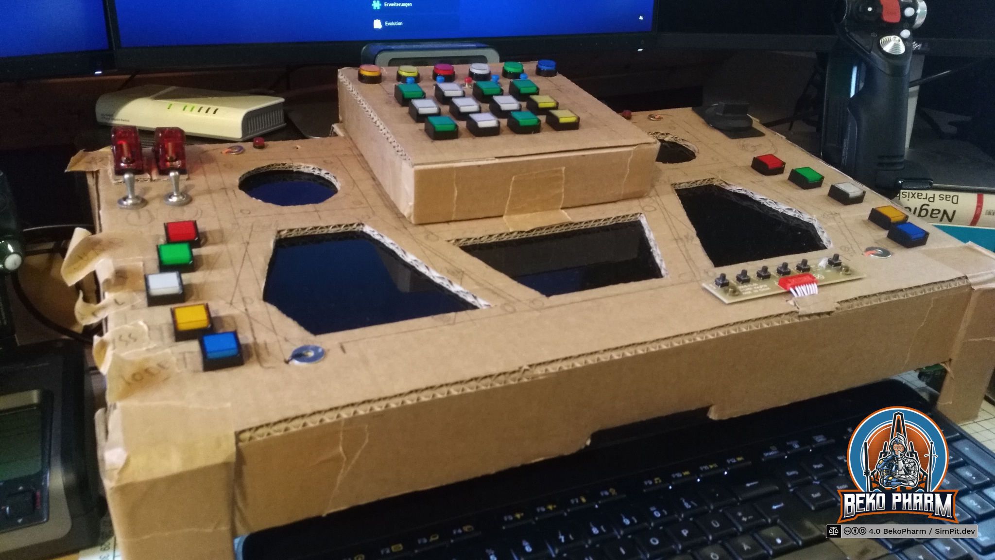
The ICP in the centre was created with a dedicated new cardboard box that was attached to the button box with tape. This also acted as a hinge so I could “open” it to work on the buttons that went there. The backlit buttons took their time to arrive and I had salvaged place holders for quite a while. I also eventually got switches with integrated LED and safety that I used for fire and forget functions like launching a missile or activating self destruct.
In the beginning I even had tape with scribbles which button does what. The backlit buttons have a cap that can be popped open for an inlay but that is a lot of work and since I was not yet sure what comes where I just used my improvised post-its for quite a while.
This content was created for an older version and is outdated. Check version 2 for an up-to-date description!
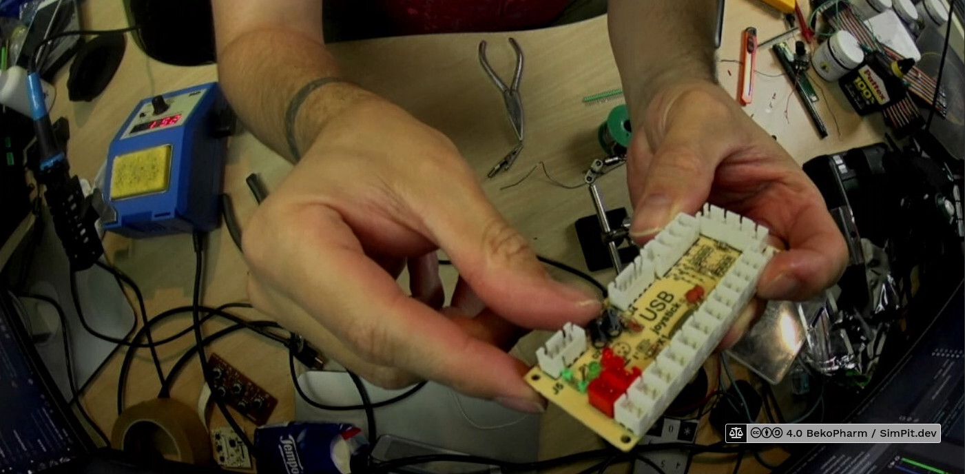
The initial controller for the cockpit was a CY-822A gamepad controller that is often found in “DIY arcade game kits” in various places. It’s a dead cheap PCB that is detected as a gamepad from most computers and while it’s kinda limited in possible inputs it does have a bunch of nice features, like a dedicated connector for backlit buttons. This is also a great place to hook in with a potentiometer to control the brightness of the backlit buttons.
There is also no reason to simply use two when the possible inputs are used up. This is a very decent little PCB that allows for a very easy DIY button without any soldering.
…we can, of course, even solder here.
CY-822A with analogue input
This is a brief description how to mod an CY-822A USB joystick controller into accepting analogue input. I’ve done this modification now with two of my PCBs and worked with both for an extended period of time without any problems. To achieve this two things have to be done.
Fire hazard
This page describes actions that may result in a fire hazard or an electric shock. Repeat at your own risk.
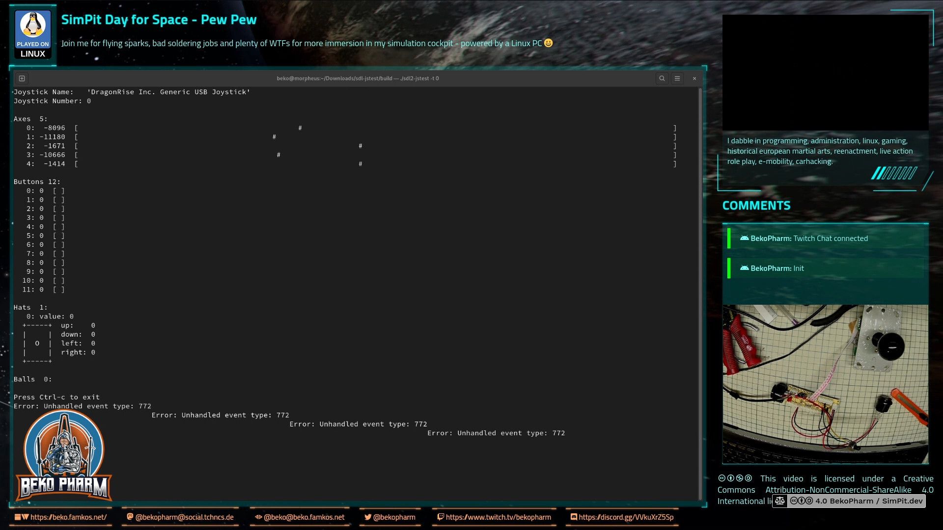
sdl2-jstest detected 5 axis
The PCB comes with 5 analogue axis according to my Linux PC and sdl2-jstest and while I’m not sure where the 5th is located a tiny modification will allow us to use at least 4 of the axis.
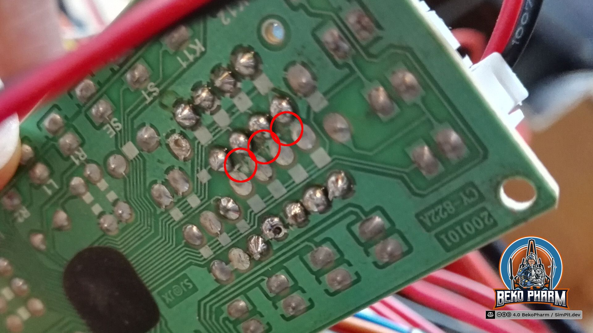
Locate the resistors R1 – R8 on the front that make up for 4 possible connections for analogue input with the use of potentiometers. There are 2 resistors with ~10k on the PCB that have to go. The 2 resistors hold 4 of the 5 axis perfectly still in the centre because the middle lane is bridged on the backside. This is the part where the conductor path has to be interrupted. Locate the central lane and simply scratch off the track with a sharp knife. Also clean all the holes of R1 to R8 so you can solder in some new pins for easier access. Use a multimeter to make sure that none of the 4 central soldering points are connected with each other any more. The upper and lower ones stay connected (Plus and GND).
Locate the central lane and simply scratch off the track with a sharp knife at the 3 indicated positions.
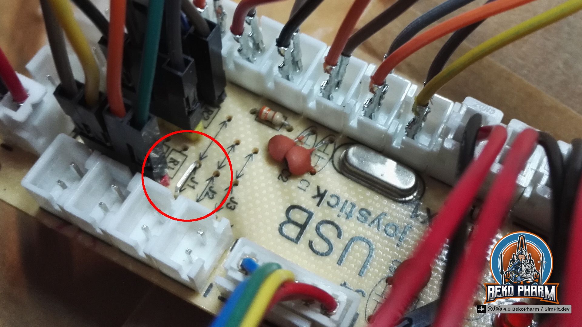
Next we want to remove the zero ohm resistor at J1 and add a wire bridge instead. Look for an resistor with a single black ring next to R2, remove it, and solder in the wire bridge next to R1. This is basically a jumper setting but with a bridge. I’ve no idea why the designer went with a zero ohm resistor and not with a bridge. My only guess is that this was cheaper for the assembly machines.
Anyway, this will make the board boot in analogue mode so we do not have to use a mode switch on power on every time. This serves two purposes: Axis are now read from input and actually send as joystick events on the USB wire while the former digital joystick connector (5 pins) is now mapped to Up/Down/Left/Right buttons – so no extra buttons are needed here any more (but can still be added, of course).
Any potentiometer should do – mine are 100k – 200k10k. YMMV.
Now it’s time to connect potentiometers as analogue inputs. This is pretty straight forward. Just make sure that the central connector goes to the centre of each axis. Change the upper with the lower pin if the direction is not as desired.
Please note that any axis that has no input attached will report a lot of jitter making your game/app go nuts. This is what the former resistors at R1 and R2 were there for. Make sure that all inputs get a potentiometer (or a resistor) to prevent this!
This content was created for an older version and is outdated. Check version 2 for an up-to-date description!
I was looking for a simple way to get data from Elite Dangerous forwarded to my cockpit but all the programs I found online are closed source solutions that have to be bought and are – as usual – Windows only. Best it would get is Android support and requires a tablet with touch functions. Nothing of this I want! The idea is to use something system agnostic that can be adjusted easily, because I want to use this for different games and not depend on a single vendor, hoping support will last and the thing work with my setup [in the future].
Using Node-RED to get status information
This was when I remembered Node-RED from usage in home automation because this is basically the same. You get a zoo of hardware, that somehow all interacts with a dashboard. All the data is on the wire and can be accessed via a web-browser. Fun enough I wasn’t the first with this idea because when I started searching for “Node-RED for simpit usage” I stumbled over the YouTube channel of Jon Back who did exactly this before (and even also used cardboard for prototyping). Encouraging and big shout out for the pioneer work!
So after installing Node-RED on my Linux PC and on my Raspberry Pi I connected the two installations via Websockets. That’s basically just entering an IP. While using MQTT is probably a better solution that I may evaluate in the future this was the easiest one because it doesn’t need an additional service.
Why I installed it twice? Well Elite drops a lot of the current game status in various JSON files, like a timestamped Journal and a Status file that holds most of the ship data I’m interested in most. The file is updated on changes and it’s easy to watch for such a change on a local filesystem. I also intend to make the receiving side as dumb as possible so I don’t have to update the code too often. I’m still uncertain what I’ll use in the end – an Arduino is also in consideration. This way I can hopefully connect other games easily as well by keeping the resulting data structure more universal and let the sender to the hard work of hammering the data into shape.
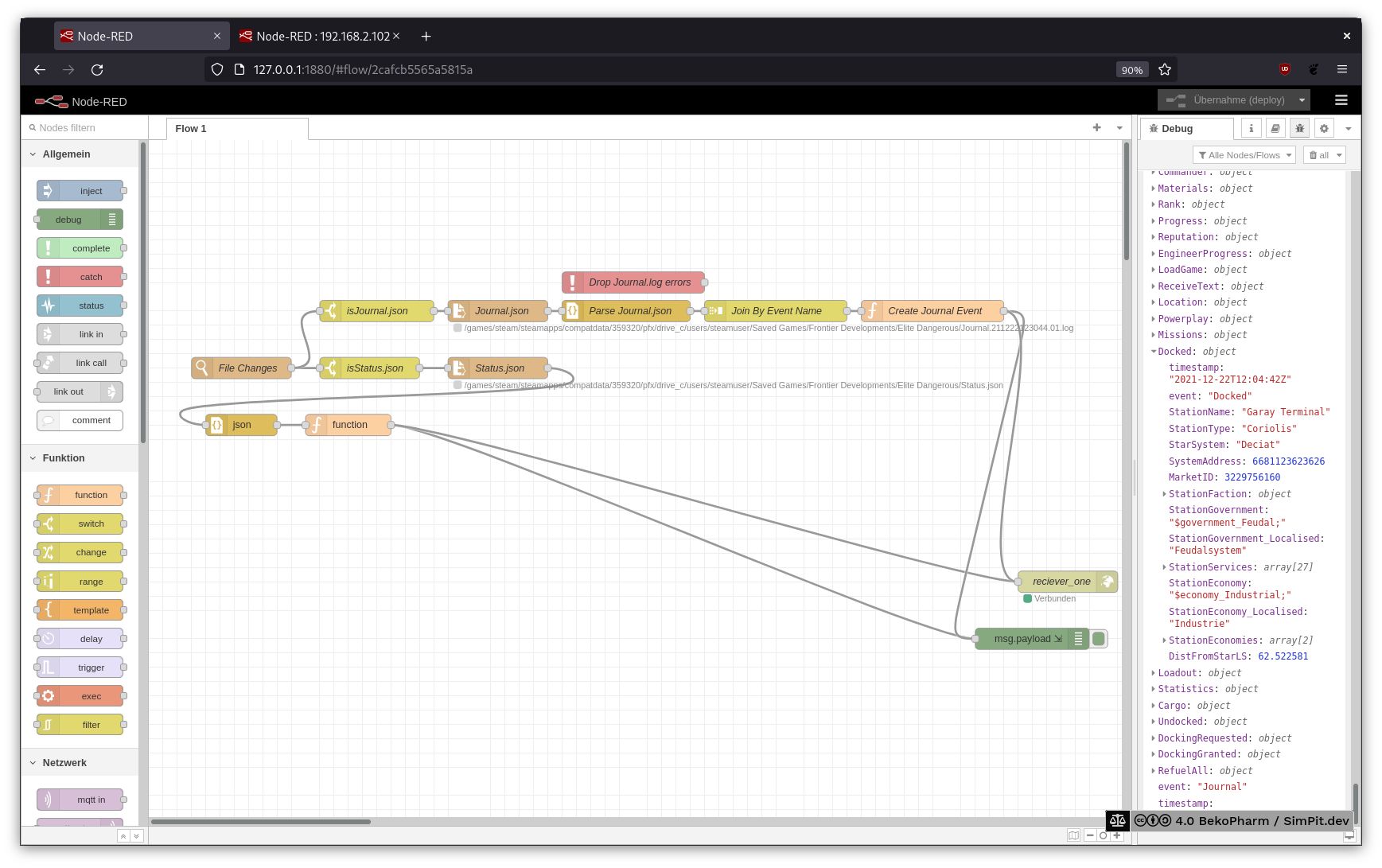
The sender flow
Short explanation what’s going on: File Changes listens for changes in my ED folder where the JSON files are located. Switches check for the file name forward it to a file opener. This one reads the file (Journal line by line) and passes the data to a JSON parser. This one forwards the parsed JSON data to a function that creates the desired data structures. Finally it is send to the receiver.
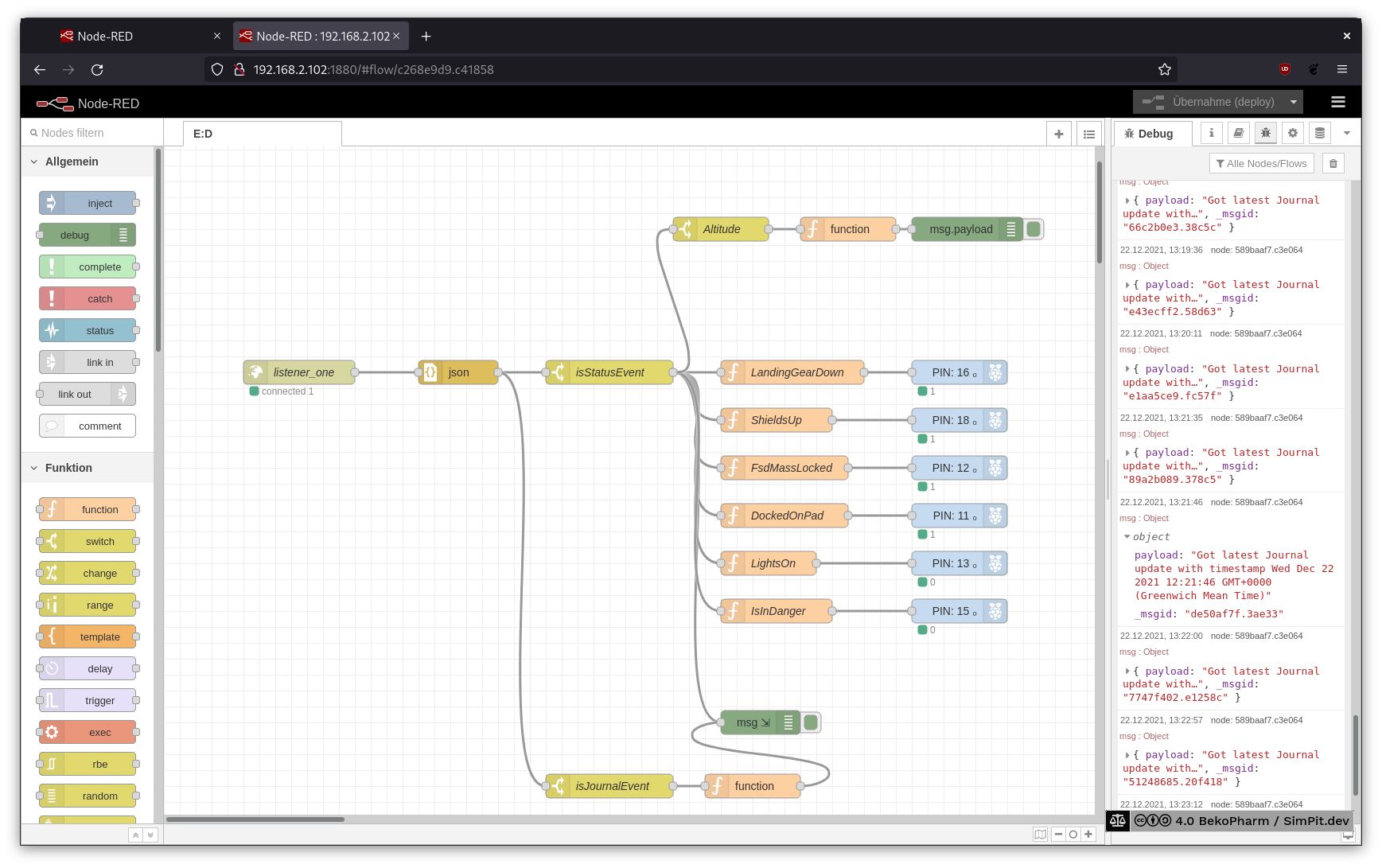
The receiving Node-RED process on the Raspberry Pi does something similar.
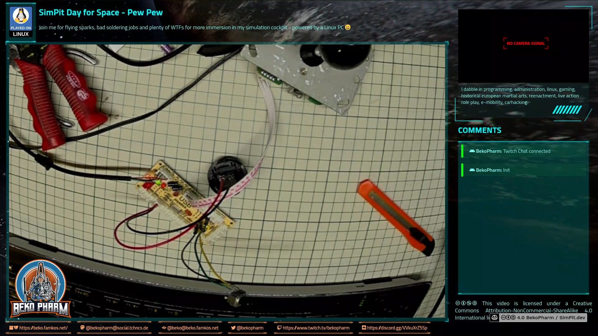
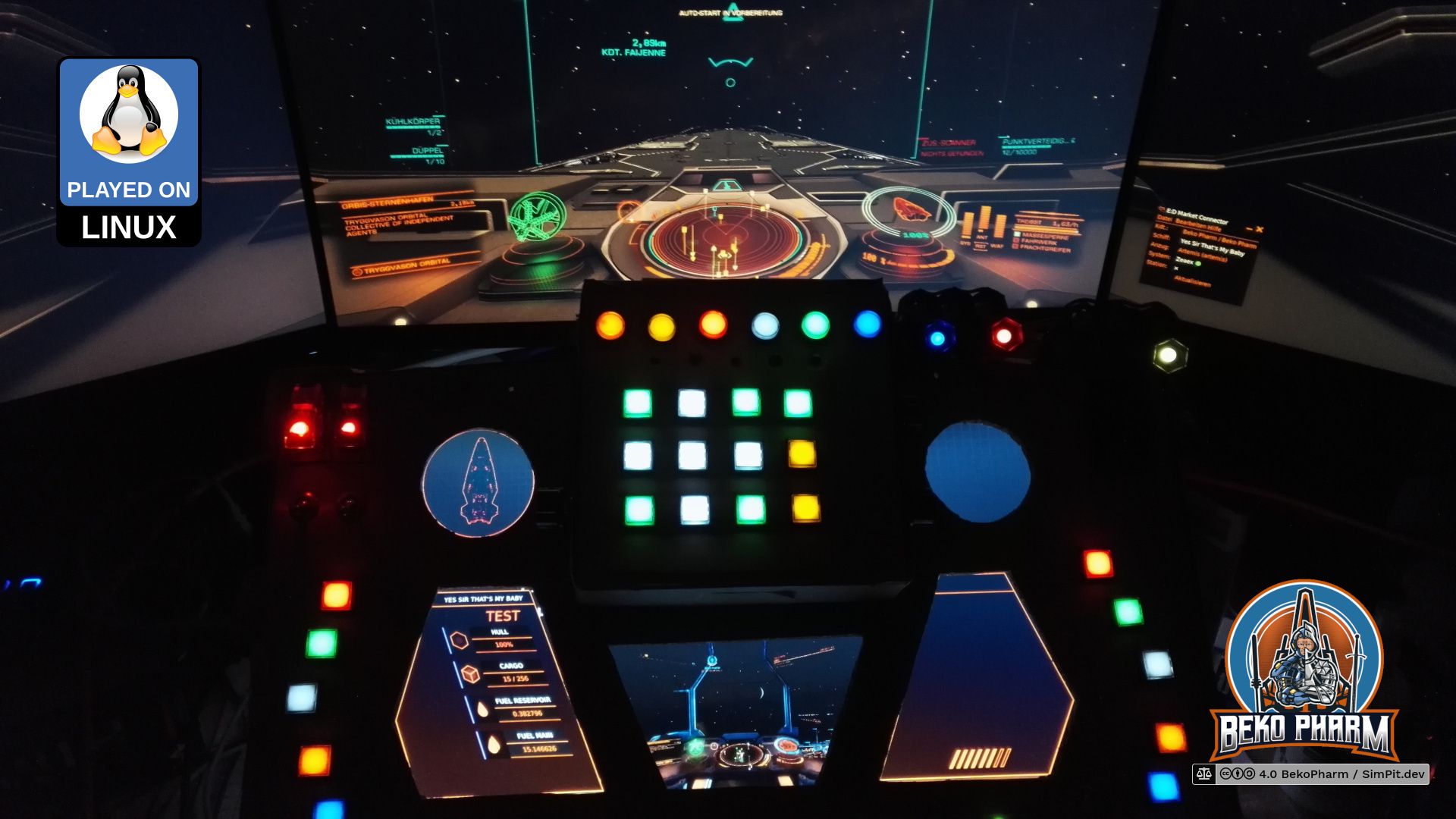
The received data is once more parsed as JSON and checked based on the event string what type of message it got. If a status event is found it’s forwarded as 0 or 1 to a GPIO where a LED will be enabled or disabled. See the short demo video of the Primary Buffer Panel in action:
This is a proof of concept that uses only a tiny bit of the available information to drive some LED I have on my custom GPIO breakout board. Later I ordered a Neopixel, a LED strip with WS2811 modules, and rewrote the receiving part.
This content was created for an older version and is outdated. Check version 2 for an up-to-date description!
Fire hazard
This page describes actions that may result in a fire hazard or an electric shock. Repeat at your own risk.
Every cockpit needs blinken lights. My status indicators were realized with a Neopixel. That’s a string of RGB LED wich indidivually addressable LED. This way only a single PIN is needed to configure all lights. It has to be a pin that can do pulse-width modulation (PWM) though so choices are limited.
There are various protocols for this. Mine consists of WS2811 modules where plenty of examples exist on the internet.
A dedicated connection is used for power and in theory all LED can be driven from that but in reality we have to keep ampere in mind so things don’t go up in flames. The string is also dead should one module break for good. Not really suited for a real *craft but hey, this is a toy and each string comes with plenty of leftoversreplacement parts 🙃
I went for this specific Neopixel because it came with the “classic” LED design. The diffusor is 12mm in diameter and the LED did fit almost perfect in their hexagonal housings. The housings are not 3D printed. That’s basically a plastic cap for protecting the bolts of the rim of a car wheel. I just cut off the cap and stuffed the LED inside. Didn’t even glue them together. A wire fixed all in place which allowed me to move the segments around. They were never attached to the panel version 1.
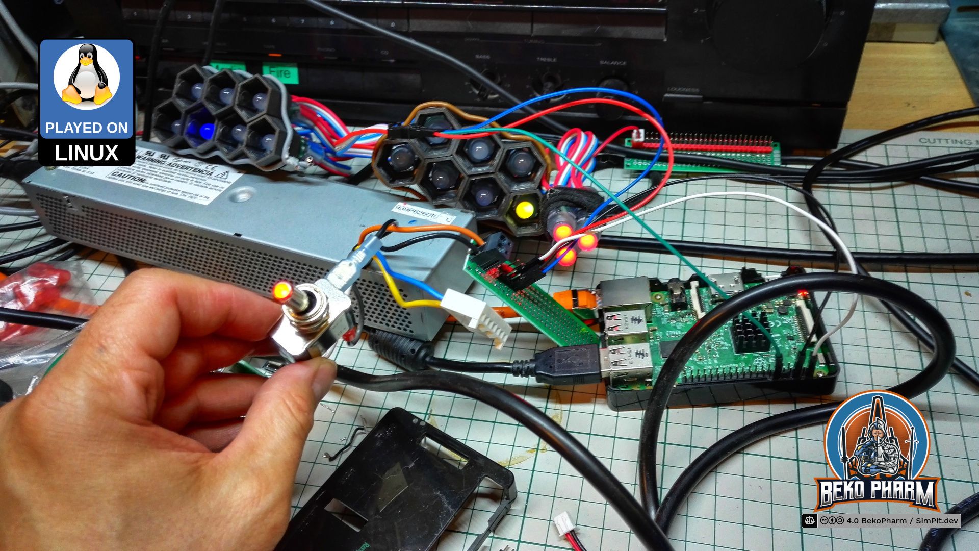
On this picture you can see that I used a cheap external power supply (PSU) to drive both, the Neopixel and the Raspberry Pi. The specific model is a VOLTEK SPEC7188B with a 5V rail rated for 3.7A and a 12V rail rated for 600mA. More than enough juice to drive all LED in my setup. A tricke line is pulled to GND to start it - the perfect place for a chunky switch for a satisfying sound. Bonus with a fancy LED.
The LEDs are controlled by Node-RED that does all the plumbing in the end.
Links
Node-RED, Low-code programming for event-driven applications
This content was created for an older version and is outdated. Check version 2 for an up-to-date description!
Fire hazard
This page describes actions that may result in a fire hazard or an electric shock. Repeat at your own risk.
Oh wow, I really do not want to show this but here we go. Please understand that this project reignited my interest in electronics. Something I have not touched (or licked) since childhood and it took quite a while to figure everything out again and get used to soldering.
So most of this is straight forward. In the beginning I used a CY-822A as controller for the buttons. This is basically a gamepad for the PC and does not require any soldering. I modded it somewhat in the end to get analogue inputs but that’s it.
Test setup of the CY-822A with backlit buttons. Test was done with uninsolated connectors. Don’t do this at home!
Buttons
Each button is simply plugged into to a free connector and that’s it. My model came with two red connector to connect backlit buttons. I attached a lot more button LEDs with a DIY power distribution board to that figuring that USB 2 would allow for 500mA so there way plenty of wiggle room. Each LED needs ~30mA.
Add a potentiometer to that power distribution and you get dimmable LED.
Most of my push buttons are momentary switches labelled as Heschen but I kinda doubt that this is really the manufacturer. I found those when I was looking for a cheaper version of the Harmony XB6 series, that I really like. The Harmony line is almost 100% more expensive though and designed for real world scenarios and kinda out of question for a low budget toy.
Officially they are 12V but do fine with 5V. Dimming works. Each LED has it’s own VCC/GND but most models I got do not even care so they are very beginner friendly. The LED is always the same just coated with colored varnish. The removable caps are colored too. They come in various shapes, round, square, four-sided and also in latching editions.
I won’t go into details about potentiometers but I wrote some on this here. You’ll find plenty of tutorials on this on the internet as well.
Display
The 17,3" display is salvaged from an old broken laptop. The exact model of mine is a LP173WD1-TLE1 by LG Display. That’s a pretty generic model using Low Voltage Differential Signaling (LVDS). Such displays need a LCD Controller to drive it. Such a 3rd party controller can be obstained for ~30 EUR depending on it’s features. There are a bunch of basic models on the market and the only difference is usually the flashed firmware and the power configuration for the backlight of the specific display. So if you have a broken laptop around salvage this and check for the exact model number and pin count on it’s backside.
As you can see mine here does HDMI, DVI, SVGA. A speaker could also be connected. The controller is powered by 12V and the vendor claims it needs 3A but in reality 1.5A are more than enough though I didn’t test it’s limit with full brightness yet. This may as well be attached to an external PSU.
ICP from the inside
Here is a peek under the hood of my “ICP”. Now isn’t that ugly? Anyway. The shiny potentiometer was used for dimming all LED on the panel. They have their own circuit so I could switch this to an external PSU later and might even switch it to 12V someday. The other potentiometers are just various axis.
What about rotary encoders?
Version 1 had no rotary encoders at all. The CY-822A was modified to be able to deal with 4 potentiometers as analogue input but that’s it.
The buttons could all share a common ground saving some wires but it was easier this way because I had to plug the wires into an existing connector in the end anyway.
Rewiring
The whole box survived several design changes and different button loadouts until I settled with it’s layout. I also replaced the CY-822A with an Arduino Mega in the end because I was running out of possible inputs on two CY-822A controllers. This is explained in more detail in version 2 however.
The rewiring also introduced a more professional power distribution and a somewhat better cable management. The only really important thing here is that the Arduino Mega is powered from an external PSU as well.
Do not let magic smoke escape
Attention though: My model here has a VIN that is not secured by a diode so the moment the external PSU is shut of it would allow all the LED to draw power from VIN resulting in an early death of the Mega. I added such a diode to the wire connected to VIN to make sure that all the extra consumers are never drawing power from the Arduino. That pin is not even rated in my datasheet!
This content was created for an older version and is outdated. Check version 2 for an up-to-date description!
The MFDs (Multi-function display) are in reality just one display that I salvaged from an old laptop. It is not running GameGlass, like so many others SimPits out there do. Mostly because I’m not a fan of touchscreens or vendor lock-in. There is also the little detail that GameGlass is simply not available for my operating system and does not know about all the Space Pew Pew I usually do.
When I was evaluating what to use to program mine I was caught between the difficult choice to learn yet another fancy framework, like Raylib, that would do OpenGL ES 2.0 without X11 on the Raspberry Pi, or OpenFrameworks, or simply go with something I knew already.
Improving situational awareness by putting the video feed of a wingman / gunner on the central MFD.
In the end I just threw the might of my CoffeeLake at it and went with React since most of the data was already available via Node-RED over Websockets anyway. Also… Arwes is just so cool (alpha version or not) 🤩 and I had some experience with it thanks to my Streaming Overlay that I also wrote with Arwes. Connecting it to Node-RED was just a matter of installing Socket.IO to transport the messages. It was all a very hacky mess but it got the job done.
The source is not available and the used alpha version of Arwes is deprecated. I rewrote the hacky mess with version 2 that is also using the next gen of Arwes.